CNC line for EPS foam wall panels: where it stands
Contents
We are designing a CNC router that cuts expanded-polystyrene (EPS) wall panels for small houses in Indonesia. The panels go up as the walls of a house and are finished with mesh and render. The machine has a 6 m bed, a moving gantry with two Y drives, a 450 mm Z axis and a belt-driven spindle with a long cutter for panels up to 300 mm thick. Everything about it is designed in the open as a build package, with CAD, drawings, electronics, firmware and a simulator, so that a local workshop can build it. Every value is preliminary until a real machine is built and measured.
The machine as a live model#
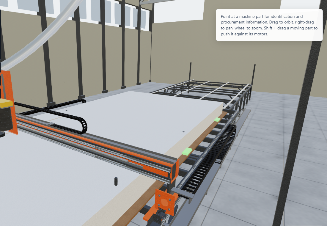
The whole machine runs in the browser as a 3D model: the frame, the gantry, the head, cable chains, the dust hose and the production cycle of loading a sheet, cutting and unloading.
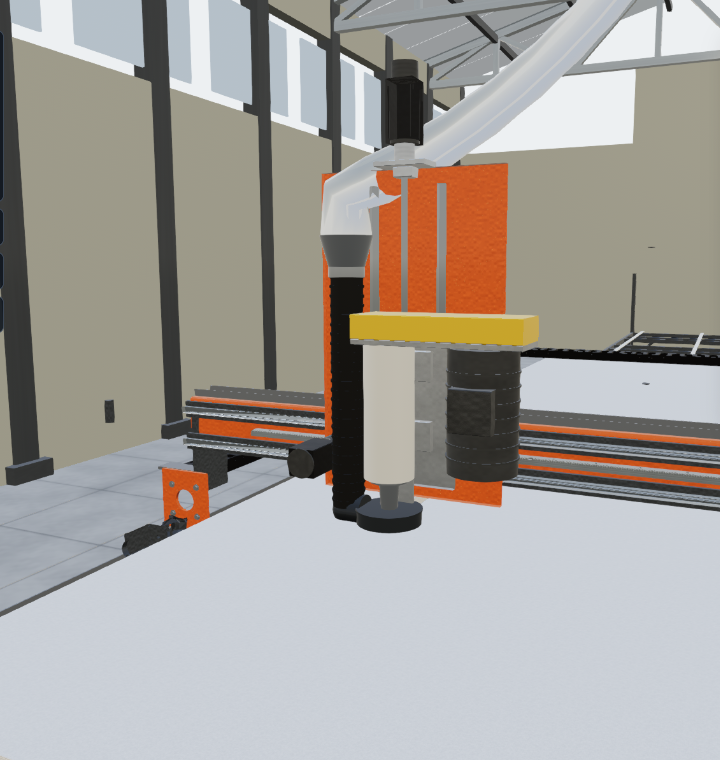
The head: the Z column on the gantry, the moving Z plate with the spindle and its motor under a belt guard, a dust hood bolted to the Z plate, and a ribbed 100 mm riser that hands over to the 150 mm overhead dust hose.
How we check it: tools, not opinions#
Each part of the project now has a tool that runs it for real and says pass or fail:
- Viewer check. It opens the 3D model in a real browser on the graphics card, lets the production cycle run, measures the frame rate and checks every pair of parts for overlap at several moments of the cut. Only contacts listed with a reason (a cutter in its holder, a block on its rail) are allowed. Latest run: PASS, 60 frames per second, no unexpected overlaps. It found and drove the fixes for a floating dust hood, a hose that ended in mid-air, parts running through each other and flickering steel surfaces.
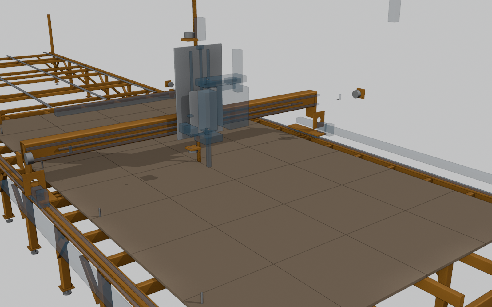
- CAD render in Blender. It builds the fabrication CAD from the same files the shop drawings come from and renders it from fixed angles. It showed that the head existed only in the 3D model, not yet in the fabrication CAD; that work is under way now.
- Board pin checker. It reads the real netlist of the controller board and checks the firmware against it. It found that the firmware read eight inputs from the wrong positions in the input shift registers, so drive alarms and limit switches would have been missed on a real machine. That is fixed, and the checker now reports zero mismatches.
- Firmware-in-the-loop tests. The controller firmware runs against a simulated machine on a PC.
The controller board#
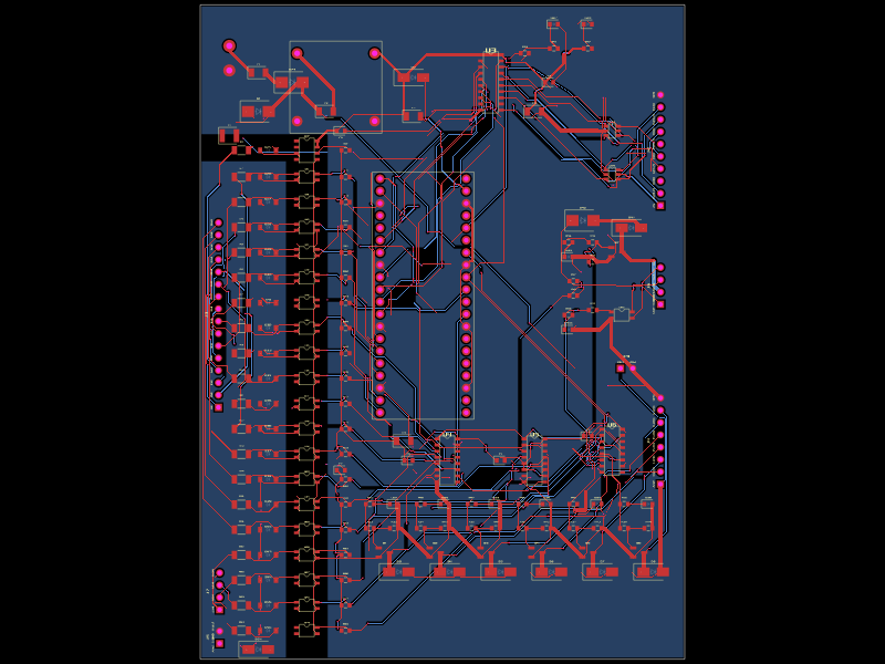
A Raspberry Pi plans the cuts, and an RP2040 board generates the step pulses and watches the machine. Today's revision adds:
- a Z brake output that releases only when the safety relay feeds it and the controller asks for it, with a fast clamp so the brake grips sooner after power is cut;
- an isolated run contact for the spindle drive;
- four more isolated inputs for the overtravel limit switches.
The board builds and routes with zero errors.
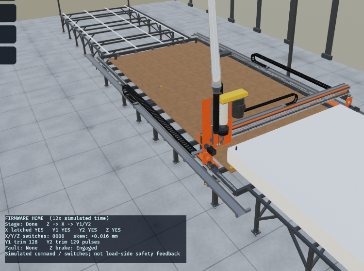
The 3D model runs the controller's own code#
The 3D model now runs the same Rust code as the controller board. Press Home and the machine homes Z, then X, then both Y sides, each to its own switch, starting from a random skew of up to 2 mm. It ends square within a few hundredths of a millimetre.
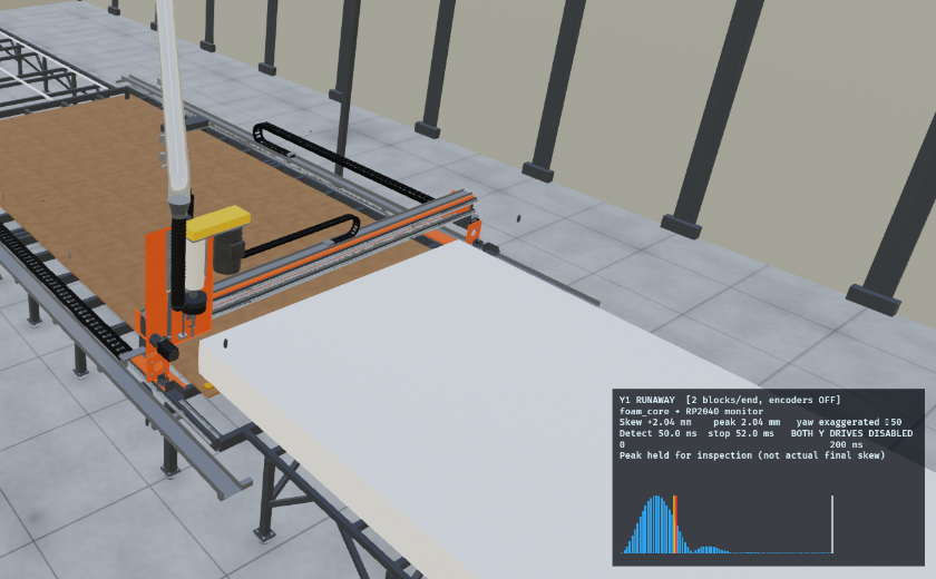
Press Y1 runaway to see what happens if one Y drive runs away: the gantry twists (drawn 50 times larger), and a plot shows the twist peaking before the drive alarm can react. You can compare more guide blocks or encoders in the same view.
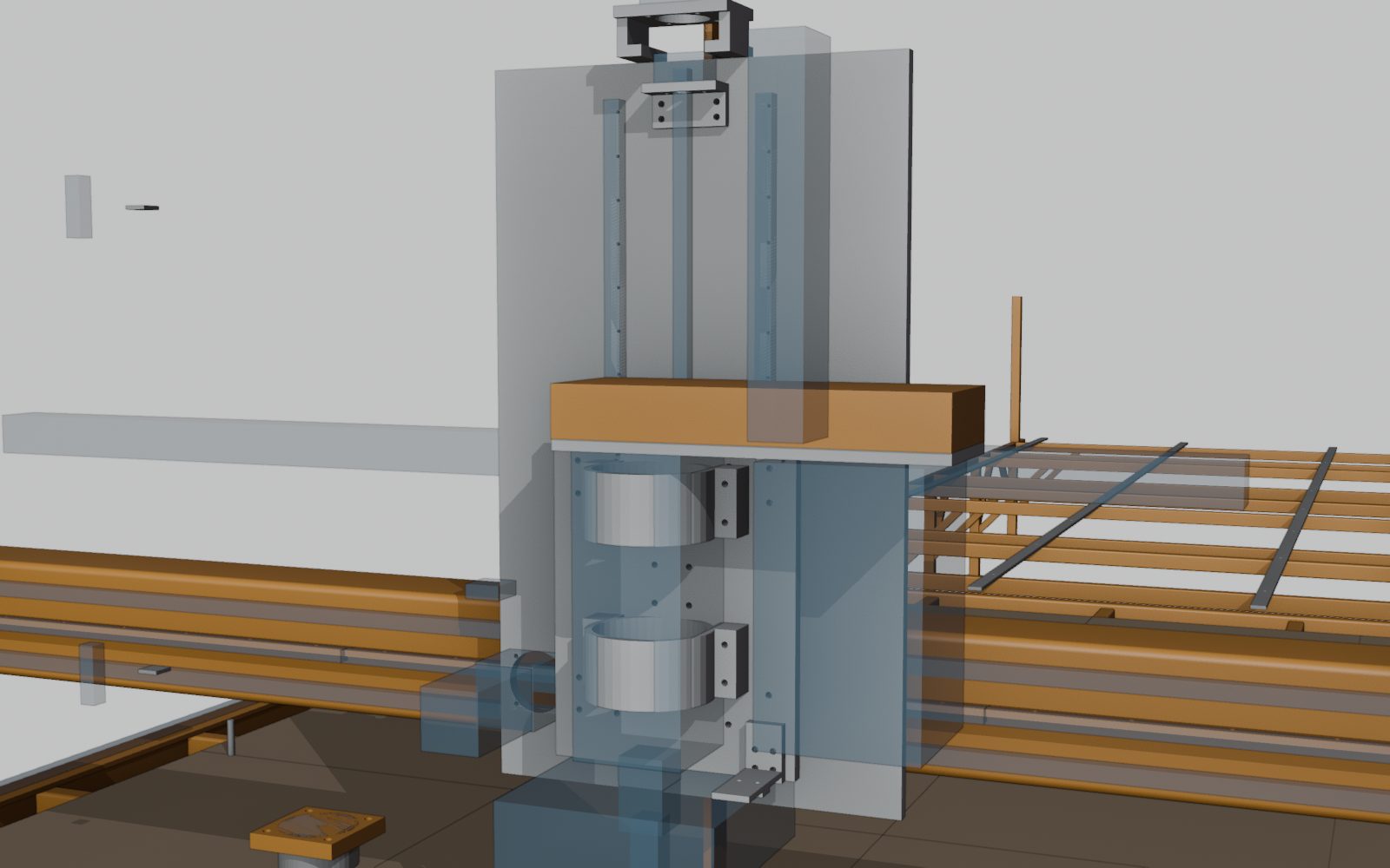
The head in the fabrication CAD#
The Z column, Z plate, spindle clamps, motor mount, ball-screw brackets, belt guard and hood bracket are now real fabricated parts with every hole, dimensioned shop drawings and a Z-axis calculation. The clash check passes with the Z axis swept through its full 450 mm.
A commissioning tool for the first machine#
A guided 50-step bring-up checks every input, output, the brake, the spindle drive contact, the emergency stop, the limit switches, the jog directions and homing on the real board, and writes a report. Against the simulator it passes all 50 steps. It catches deliberately injected wiring faults and names the step and the cause.
What works now#
- Homing and squaring: the gantry homes each side to its own switch. In simulation it starts 2 mm out of square and ends within 0.05 mm, and every fault case stops it safely.
- Frame: the rail deflection under load is 0.13 mm against a 0.72 mm limit.
- Drawings: 38 dimensioned shop drawings, weld drawings and a cut list.
- Gantry twist: a study of the twisting that happens if one Y drive runs away found that the twist peaks in about 35 ms, faster than a drive alarm can react. So the fix has to be mechanical (more guide blocks or a skew stop) or a direct measurement (encoders), not a faster alarm.
What comes next#
- The head (Z axis, spindle mounts, guards) as fabrication CAD with drawings and calculations.
- A commissioning tool that walks a technician through checking every input, output, brake, homing step and safety function on the real board.
- The choice of gantry-twist protection, then building and measuring the first machine.
One person, many companies, one coin. Every project I build sends a share of its revenue back to buy $BERLIAN on the open market, and every buy is published with its transaction.
More from Gor Berlian
CNC foam-panel router: assembly in 42 pictures
42 steps, each with a picture of the whole machine and a close-up of the parts added. English and Indonesian.
1,008,000 gravity
TradJS 4.7.0 in testing: 1,902 tests and 118 browser steps on the development branch
Repository: https://github.com/7flash/TradJS · On npm today: tradjs 4.6.5 · Tested here: the 4.7.0 development branch, 19 November 2026, Bun 1.4.3 on Windows 11.
The Plain Web Stack
TradJS, sqlite-zod-orm and measure-fn: what they are, how they are tested, and when to use them. A short book, November 2026.